
Principles
- Differentiate component functionality of NSX stack infrastructure components
- Compare and contrast with advantages/disadvantages of topologies (star, ring, etc.) as well as
scaling limitations - Compare and contrast VMware NSX data center deployment models
- Prepare a vSphere implementation for NSX
References
- VMware NSX Network Virtualization Design Guide
- vSphere Networking Guide
- NSX Administration Guide
Differentiate component functionality of NSX stack infrastructure components
- List and describe NSX Components: Design Guide
VMware NSX is the network virtualization and security platform for the software-defined data center and virtualization to your existing network. NSX is composed of several components.

Physical Network
NSX allows logical or “overlay” networks to be configured on an existing physical IP network. It is vendor-agnostic as long as the underlying physical network can support an MTU of 1550 bytes or more. An MTU of 1600 is recommended.
Data Plane
The NSX vSwitch is an enhanced version of the Distributed Virtual Switch (DVS) that implements the NSX Data Plane. VMWare Installation Bundles (VIBS) are installed on ESXi hosts to provide NSX Switch features to the DVS.

Embedded in the ESXi kernel, NSX VIBs provide various services including:
- Distributed Routing
- Distributed Firewall
- VXLAN -> VLAN Bridging
Abstracting the physical network in the ESXi Hypervisor, the NSX vSwitch allows logical networks to be de-coupled from the physical network topology to some extent, thereby allowing flexible network topology implementation through the use of VXLANs.
Routing and Switching
The NSX Switching Fabric is implemented with VXLANs that are layered over (i.e. configured on top of) an existing physical network infrastructure. However the NSX L2 topology is largely independent of the underlying physical network – as long as the underlying network provided the end to end connectivity needed by ESXi hosts, the VXLAN L2 Topology can be configured in any manner supported by NSX.
Routing functions are provided in one of two ways:
- Distributed Logical Router (DLR)
- Edge Services Gateway (ESG)
Typically the DLR is optimized for East-West communication with the NSX Infrastructure and the ESG is optimised for North-South communication.
Physical Network Interface
Standard network and security functions are provided by NSX including Routing & Switching. Communication between the NSX Data Plane and the physical network (VXLAN to VLAN) can be achieved in one of two ways using NSX Edge Service Gateways:
- Layer 2 (L2) Bridging
- Layer 3 (L3) Routing
NSX Edge
NSX Edge Services Gateways provide network edge security and gateway services in a virtualized network. You can install an NSX Edge either as a Distributed Logical Router (DLR) or as an Edge Services Gateway (ESG).
- Distributed Logical Router
Provides distributed routing with tenant IP address space and data path isolation. Virtual machines or workloads that reside on the same host on different subnets can communicate with one another without having to traverse a traditional routing interface. The DLR supports OSPF, BGP and IS-IS.
- Edge Services Gateway
Acts as a barrier/perimeter between logical and physical networks and can offer multiple services including
-
- Firewall: Acts as a Perimeter Firewall between Logical and Physical networks
- Load Balancer: Provides L4-L7 Load Balancing with support for Proxy and In-Line mode as well as SSL Termination
- NAT: Provides both Source and Destination NAT Services
- DHCP: Provides native DHCP Services along with DHCP Forwarding
- Routing: Static and Dynamic Routing with support for OSPF, IS-IS and BGP
- VPN Services: Various VPN services including SSL, IPSec and L2 VPN.
Distributed Firewall
The Distributed Firewall controls the flow of traffic between tenant VXLANs with Security Groups and Policies. In the example below Web, App and DB VMs are placed on separate networks connected through the DLR. Traffic is isolated by the Router and Firewall Policies applied by a Distributed Firewall control traffic flows between networks. Note: The Distributed Firewall is not part of the DLR and there is no dependency between them.
Security Policies are applied directly at the ESXi Kernel and vNic level. Further inspection of network traffic is possible through Integration with third party vendors such as Fortigate and Palo Alto. Services include Anti-Virus, Anti-Malware and IDS/IPS. The process for 3rd party integration is known as “Service Insertion”.

Control Plane
The NSX Control Plane operates separately from the Data Plane. Control and Data traffic never intersect i.e. Control Plane traffic is always kept separated from Data Plane traffic.
The Control-VM deployed for a DLR operates at the Control Plane. It handles routing updates to/from NSX Controllers but is not directly involved in the forwarding of user traffic – that task is handled by the ESXi Hypervisor at kernel level.

NSX Controllers
NSX Controllers are the central control point for all logical switches within a network. They maintain information from Virtual Machines, Hosts, Logical Switches, and VXLANs
- Controllers are always deployed in clusters of 3 –in Single Site and Multi-Site deployments
- Controllers not required where Multicast replication is used: Hybrid and Unicast only

User World Agent (UWA)
- The UWA is composed of netcpad + vsfwd daemons on ESXi hosts
- Uses SSL to communicate with NSX Manager
- Mediates between NSX Controller and Hypervisor Kernel Modules except DFW
- Retrieves information from NSX Manager through Message Bus Agent

Management Plane
- Built by NSX Manager
- Single Point of configuration
- REST API entry points

The NSX Manager is the centralized network management component of NSX, and is installed as a virtual appliance on any ESXi host in your vCenter Server environment. One NSX Manager maps to a single vCenter Server.
Consumption Model
- Driven through NSX Manager UI through vSphere plugin
- NSX can be configured through:
- vSphere Web Client
- CLI
- REST API
- Out of the box integration with:
- vRealize Automation
- vCloud Director
- VMware Integrated OpenStack with Neutron plugin
Compare and contrast with advantages/disadvantages of topologies (star, ring, etc.) as well as scaling limitations
Bus
Bus Topologies connect devices in a line with shared access to the physical data carrying media. Early Bus Topologies used Coaxial cables to connect devices.
- Advantages
- Simplicity
- Scalability
- Low cost to implement with modern switching hardware
- Disadvantages
- Difficult to troubleshoot
- Coax cable networks to not scale
- Shared bandwidth means the bus can easily become saturated
- Network becomes segmented if there is a break in the cable
Star
In a Star Topology, devices are connected to a central Hub or Switch and all communication flows via this central device.
- Advantages
- Centralised management
- Resilient to individual failures i.e. if one host goes down the remaining devices are not affected
- Expandable
- Disadvantages
- Potential bottleneck at the Hub devices
- Generally higher cost
- Single point of failure at the Hub
Ring
Ring Topologies connect devices in a circular fashion. Early examples of such a topology include FDDI and Token Ring
- Advantages:
- High Speed
- Minimal Packet collisions due to orderly, single file flow of data
- Scalability
- Disadvantages
- Traffic passes through each devices on the network
- Devices can be “hot” added i.e. the network goes down to bring a new device online
Compare and contrast VMware NSX data center deployment models
Supported Deployment Models
Physical Router as next hop
This is the most basic supported topology whereby a single DLR is connected directly to a Physical Router through a VLAN backed Physical Logical Interface (pLIF). The flat nature of this topology means that the DLR is responsible for both East-West and North-South routing.

A drawback of this design is that all ESXi hosts in the Compute Cluster must have access to the uplink VLAN. Typically, NSX Edges are placed in a separate dedicated cluster and likewise tenant VMs in a dedicated tenant cluster. Ordinarily therefore North->South traffic would flow from the compute cluster across to the NSX cluster before exiting the environment.
However in this case, each and every Compute Cluster needs access to the Uplink VLANs in order to pass Egress traffic as shown below.
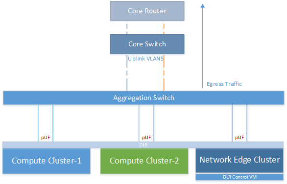
Some organisations may consider this to be a security risk because tenant traffic is directly exposed to the outside world without a perimeter firewall at the NSX Layer. However it should be noted that it is of course entirely feasible that a physical firewall could be placed north of the core router shown in the diagram above.
Single Tier – NSX Edge as Next Hop (Enterprise Topology)
In this deployment model, and NSX Edge Services Gateway is placed between the DLR and external network. The DLR in this instance no longer needs access to the uplink VLAN as only the ESG will be connecting to the physical network.

Advantages:
- The Compute Clusters no longer need direct access to the physical network since the uplink is via an ESG connected through a VXLAN transit network
- As the uplink is now decoupled from the logical network side, this provides greater freedom to expand/modify the tenant topology without affecting the physical network, providing greater autonomy to network designers
Disadvantages
- All north-south traffic passes through a single ESG, potentially introducing a bandwidth bottleneck and also a single point of failure. This however can be mitigated by configuring multiple ESGs at the uplink using Equal Cost Multipath (ECMP) as of NSX 6.1.
Two Tier Topology (Multi-Tenant)
Where multiple tenant share the same NSX infrastructure, it may be necessary to separate the network topology for each one due to different requirements. In additional to security concerts, each tenant may have different requirements for services such as Firewall, Load Balancer, and VPN.
In the deployment model shown below, each tenant is assigned a dedicated DLR, providing a self-contained logical network environment beneath the ESG. Routing towards the external network can be achieved either through the use of static routes or a dynamic routing protocol such as OSPF.

One disadvantage of this topology is that is does not scale beyond 9 tenants. The ESG is a VM limited to 10 network interfaces in total. As one of these is used for the uplink, that leaves behind 9 vNics for tenant connections. Ideally there should be two uplinks configured on the ESG, further reducing the maximum number of tenants to 8.
Note: In this topology each tenant must have unique IP addresses in order to be routable from the ESG.
ESG Trunk Interfaces
To help overcome the scaling limitations of the 2-tier topology, trunk Interfaces were introduced in NSX 6.1. Using sub-interfaces, the ESG can trunk multiple connections to DLRs over a single VXLAN connected interface. A total of 200 sub-interfaces can be configured on a single ESG spread across all available vNics in NSX 6.1.2 – check the release notes for the latest release for current scaling limits.

Each DLR peers with a sub-interface on the ESG. BGP and Static routes are supported in NSX 6.1 with OSPF supported from 6.1.3 onwards.
Scalable Topology (Service Provider)
In this deployment model the 9 interface limitation is removed by adding a 3rd tier to the network for aggregation and northbound connections.
Each tenant may be configured with its own ESG and DLR pair, providing a self-contained environment with dedicated Load Balancing, North-South Firewall etc. Trunk Interfaces can be combined with this topology to provide flexible configuration options to meet customer requirements.

Additionally, this model allows overlapping IP Addresses to be used in the tenant address space. NAT services can be utilized on the Tenant ESG to isolate traffic between tenants. Destination NAT is required for inbound connections towards the tenant environment. Likewise, a Source NAT is required for northbound traffic from the tenant.
Care should be taken to configure a non-conflicting unique address space on the Transit VXLAN, one this is also large enough to cater for the planned number of tenants and their services. Bear in mind that inbound service towards tenants may consume multiple IP Addresses on the Transit VXLAN e.g. HTTP, HTTPS, SSH, RDP = 4 Transit IPs for each tenant + 1 Source IP for egress traffic = 5 in total. Alternatively Port Address Translation may be utilised to support multiple NAT services on a single IP Address. Either way the network design should take this into account from the outset.
Unsupported Deployment Models
Hierarchical DLR
DLRs should not be connected in a hierarchical manner as shown below. An ESG should be used in place of “DLR Instance 3” instead.

Shared DLR -> ESG Peering
DLRs are not permitted to share a VXLAN for peering purposes as shown below. Each DLR should connect to the ESG over a separate VXLAN. Where more than 9 DLRs are need, either the Scalable Topology may be used or ESG Trunk Interfaces as discussed above.

Prepare a vSphere implementation for NSX
Pre-Requisites
- At least one Distributed virtual switch (dVS)
- The MTU for Ethernet frames on the transport network must be set to 1600 or greater on the NSX Transport VLAN. (NSX introduces an extra header into Ethernet frames).
- Enable L2 IGMP Snooping on the NSX Transport VLAN to allow local Multicast forwarding of VTEP traffic. An IGMP Querier should be configured on the Transport VLAN. If Multicast is not required, then Unicast can be used instead
Installation Workflow
- Deploy NSX Manager
- Register NSX Manager with vCenter
- Deploy NSX Controllers (x3)
- Prepare ESXi Hosts (install VIBs)
- Configure Logical Networking:
- Configure Segment ID Pool and Multicast Address Range
- Configure VTEPs
- Configure Transport Zone
Distributed Firewall
NSX Controllers and Logical Networking are not required for Distributed Firewall i.e. just install NSX Manager and register with vCenter to get started with DFW.